Privacy statement: Your privacy is very important to Us. Our company promises not to disclose your personal information to any external company with out your explicit permission.
There are many tools commonly used by electricians. Clamp-type ammeters are one of the common ones. They are called clamp meters. Clamp meters are sometimes called clamp meters and clamp meters. AC/DC clamp meters are also necessary for daily maintenance work of electricians. One of the test tools is mainly used to test voltage, current, frequency and other related parameters, requiring high test resolution, test accuracy and more test functions.
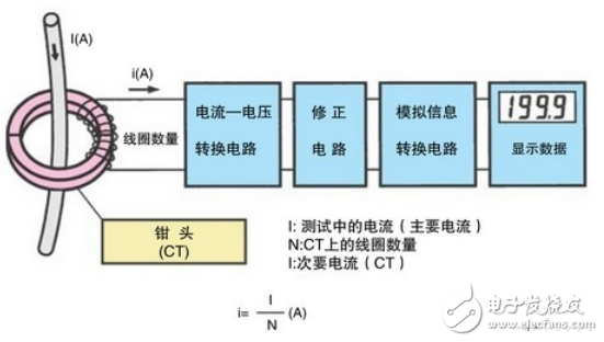
First, the AC clamp meter measurement principleThe clamp meter consists essentially of a current transformer, a clamp wrench and a counter-reactive instrument with a rectifying magnetoelectric system. Therefore, the clamp meter is actually a combination of current mutual inductance and ammeter. Its closed core is opened, and the current-carrying conductor is clamped into the core of the core. This wire is equivalent to the primary winding of the current transformer with a number of turns 1. A secondary winding is wound around the core and connected to the measuring instrument, and the value of the measured current can be directly read. It is very convenient to use the clamp meter to measure current without disconnecting the circuit.
Normally, the operation of an AC clamp ammeter follows the CT principle, which is commonly used for current to obtain magnetic flux through a conductor. Assuming that the current through the conductor is the main current, we can obtain a current proportional to the main current by electromagnetic induction generated by the secondary coil of the clamp (the secondary coil is connected to the circuit of the object to be measured). This allows us to get the AC current (using a digital clamp ammeter)
Refer to the flow chart below specifically:

Read the instructions carefully before use to find out whether it is AC or AC and DC. The well is mechanically zeroed.
Select the appropriate range, first select the large, then select the small range or look at the nameplate value estimation, the voltage of the circuit under test can not exceed the value indicated on the clamp meter, otherwise it will easily cause grounding accident. Or cause electric shock.
The current of one phase conductor can only be measured at a time. The conductor to be tested should be placed in the center of the clamp window. It is not possible to measure the multiphase conductors in the window.
Before measuring the clamp meter, you should estimate the magnitude of the current to be measured before deciding which range to use. If you can't estimate it, you can use the maximum range and then change it to make an accurate reading. Small current gears cannot be used to measure large currents to prevent damage to the meter.
The jaws should be closed tightly when measuring, and if there is noise after closing. Open the jaws and reclose them once. If the noise still cannot be eliminated, check whether the joint surfaces on the magnetic circuit are clean and clean. If there is dust, wipe it clean.
Due to the low accuracy of the clamp ammeter itself, when measuring small currents. The following method can be used: the wire of the circuit under test is wound a few times, and then placed in the jaw of the clamp meter for measurement. At this time, the current value indicated by the clamp meter is not the actual value to be measured. The actual current should be the reading of the clamp meter divided by the number of turns of the wire winding. That is: reading = indication value & TImes; range / full bias & TImes; number of turns.
After the measurement is completed, the transfer switch should be placed at the leftmost range.
Do not operate with electricity during maintenance to prevent electric shock.

1. Insert the red test lead into the “VΩHz” jack and the black test lead into the “COM” jack.
2. Place the function range switch in the resistance file and connect the test leads to the resistor under test.
3. Read the measurement results from the display.

Author:
Ms. Cathyleen wang
Phone/WhatsApp:
July 19, 2023
E-mel kepada pembekal ini
Author:
Ms. Cathyleen wang
Phone/WhatsApp:
July 19, 2023

Ms. Cathyleen wang
Tel:
+86-0574-13957831201
Fax:
E-mail:
Tapak Mudah Alih


Privacy statement: Your privacy is very important to Us. Our company promises not to disclose your personal information to any external company with out your explicit permission.

Fill in more information so that we can get in touch with you faster
Privacy statement: Your privacy is very important to Us. Our company promises not to disclose your personal information to any external company with out your explicit permission.